
Having refrigerant on site does not guarantee a reliable supply at the charging station. The real engineering problem lives in the gap between “we have refrigerant in the building” and “we have usable liquid refrigerant at the charging point, right now, at the pressure and flow rate the process requires.”
On an OEM production line, the charging equipment can only be as accurate and as consistent as the supply feeding it. If the liquid line flashes to vapor, if cylinder pressure sags as the container empties, or if the piping cannot move enough flow to several stations at once, the charge quantity drifts and the line stalls. This guide covers how refrigerant supply systems work in manufacturing, what drives the choice between supply sources, how transfer pumps and piping interact with production requirements, and where the real design decisions sit.
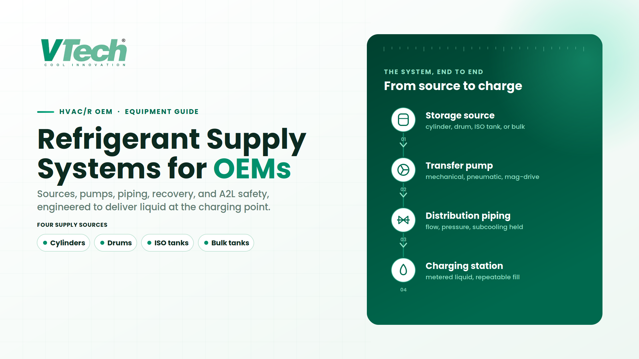
A refrigerant supply system delivers refrigerant from a storage source to the charging equipment under the conditions the manufacturing process requires: a steady flow of liquid refrigerant, at adequate pressure, delivered safely and repeatably. The charging equipment then meters a precise quantity into each product. The two are separate systems that must be engineered to work together.
Who this guide is for
This is written for OEM manufacturing and process engineers, production managers, and plant engineers who specify or upgrade refrigerant charging infrastructure. Field service technicians and contractors installing residential splits will find the context different: continuous production demand, multiple charging stations, residual-refrigerant economics, and A2L safety at scale are structurally different from field service work.
What is a refrigerant supply system?
A refrigerant supply system is everything between the storage source and the point where refrigerant enters the charging equipment. It begins at the container or tank and ends at the inlet of the charging station. Its job is to deliver a continuous, reliable flow of liquid refrigerant at adequate pressure to every charging station, without interruption, contamination, or phase change.
That is a different job from charging. The refrigerant charging equipment controls how much refrigerant goes into each product unit. The supply system does not care how many grams enter each unit; it cares that liquid, at the right pressure, is available the moment the charging station calls for it. In a liquid-charging process, the accuracy of the fill depends directly on the stability of the supply at the charging inlet.
How does a refrigerant supply system work?
The process runs in a clear sequence, though the exact configuration varies by application. Not every system uses the same pump, pressure arrangement, instrumentation, or piping layout.
Types of refrigerant supply sources
Four supply-source options cover most OEM applications, and each shapes the refrigerant supply equipment built around it. The right choice depends on production volume, delivery requirements, site infrastructure, and operating cost, not on capacity alone.
Refrigerant cylinders
Cylinders (commonly around 100 lb nominal capacity, though this varies by refrigerant and manufacturer) suit lower-volume operations or development lines where demand does not justify larger infrastructure.
The constraint that catches teams out: as liquid is withdrawn, cylinder pressure drops. In cooler ambient conditions or at higher withdrawal rates, the remaining liquid may not generate enough vapor pressure to push refrigerant to the charging point at adequate flow. Heater blankets are one method some operations use to maintain cylinder pressure, but whether external heating is appropriate depends entirely on the refrigerant, the cylinder rating, and the manufacturer’s instructions. Not every refrigerant or container tolerates it, and external heating should never be applied as a generic fix.
The deeper issue is the liquid-to-vapor transition. Once the liquid level drops below the withdrawal point, the system pulls vapor, and a liquid-charging process cannot use vapor-phase refrigerant. That final portion of the cylinder becomes residual inventory, which is a real cost question addressed later in this guide.
Half-ton and one-ton drums
Drums scale the source capacity for medium-volume production, and the withdrawal arrangement changes with them. You are typically looking at a mechanical or pneumatic pump to move liquid from the drum into the distribution system, because relying on vapor pressure alone across longer runs or at higher flow rates becomes unreliable.
Industrial weighing systems under the drums track remaining inventory in real time, which matters for production planning and changeover scheduling. The specific pump, withdrawal method, and pressure requirements need validation against the refrigerant’s physical properties and the container’s design. A pump sized for R-410A will not necessarily perform the same way on R-32 or R-454B.
ISO tanks
Where drums create too many changeovers but a permanent bulk installation is not justified, ISO tanks offer an intermediate option that sits between smaller containers and fixed bulk storage. The capacity figures indicated by the client (roughly 15 to 25 tons) are indicative only; actual container specifications vary by manufacturer and refrigerant and should be confirmed against the specific tank model before committing to a layout.
One point surprises teams new to ISO tanks: a leased tank arrives with refrigerant inside, but it does not come with the pumps, piping, instrumentation, or safety infrastructure needed to deliver that refrigerant to the charging stations. The delivery infrastructure, and any leasing or rental cost, is the end user’s responsibility.
Bulk refrigerant tank systems
High-volume OEM lines may warrant permanent bulk storage, which the client references for the largest operations. The economics depend on production volume, delivery frequency, refrigerant cost at bulk versus smaller quantities, and the capital required for tanks, pumps, piping, safety systems, and site modifications.
A bulk tank is not automatically the right answer for every large operation. The total system cost includes the storage vessel, transfer equipment, distribution piping, safety provisions, permitting, ongoing maintenance, and the operational complexity of managing a large refrigerant inventory on site. Bulk systems are often delivered as a turn-key package that includes the delivery system.
A note on capacities: the cylinder, drum, ISO-tank, and bulk figures above follow the client’s supplied material and are indicative. Confirm the exact nominal refrigerant mass (versus container gross weight) against the specific container and refrigerant before specifying a system.
How to choose refrigerant transfer pumps
The transfer pump, often supplied on a refrigerant pumping skid, is the heart of the refrigerant delivery system. Three types of refrigerant transfer pumps come up repeatedly in OEM applications: mechanical (motor-driven), pneumatic (air-driven), and magnetic-drive. Rather than declaring a winner, the useful question is what actually drives the selection.
Mechanical pumps: motor-driven units whose role and operating requirements (flow, pressure, materials, maintenance) must be checked against the refrigerant and duty.
Pneumatic pumps: air-driven units whose selection depends on the complete installation, including the available air supply and the full operating envelope.
Magnetic-drive pumps: seal-less units that eliminate shaft seals, which removes one leak path, but introduce their own constraints around flow range and particulate sensitivity.
Beyond pump type, several factors decide the selection:
- Refrigerant compatibility. Not every seal material, gasket, or wetted metal works with every refrigerant, especially as the industry moves toward A2L and A3 options with different solvent properties.
- Flow rate and delivery pressure. These depend on how many charging stations the pump feeds and how far the refrigerant travels. A pump that serves a single station 20 feet away will not necessarily hold adequate liquid delivery across 200 feet of piping to four stations.
- Distance and number of stations. Longer runs and more stations raise the required flow and the pressure the pump must overcome.
- Duty cycle and production demand. A pump running intermittently on a low-volume R&D line faces different wear than one running near-continuously on a line charging hundreds of units per shift.
- Material and maintenance constraints. Component compatibility and service requirements shape both reliability and total cost.
Select the pump for the actual refrigerant and operating conditions, not simply the nominal production volume. There is no universal best pump, because refrigerant, layout, flow, pressure, and duty interact in ways a generic recommendation cannot capture. The final selection needs application-specific engineering review.
Refrigerant distribution piping design considerations
Piping looks straightforward until the liquid line flashes. That is the moment a team discovers that pressure drop, heat gain, and elevation change consumed the subcooling margin, and what arrives at the charging station is a two-phase mixture instead of clean liquid.
Flow rate and pressure drop
Required flow, piping layout, fittings, and distance all shape the conditions at the filling point. Every fitting, valve, and direction change adds pressure loss that erodes the delivery margin, so the layout is a design variable, not an afterthought.
Refrigerant compatibility and component ratings
Pipe material, seals, valves, and instrumentation must be verified as compatible with the selected refrigerant and rated for the applicable operating pressures and temperatures. The refrigerant determines the thermodynamic properties, material compatibility, and pressure class the components must meet.
Thermal expansion and temperature changes
Long runs move as temperatures change, so thermal expansion needs to be accommodated in the design rather than absorbed by the fittings. Ambient temperature range is a design input, not a detail.
Piping layout and maintenance access
Isolation valves and service access points should be planned into the layout, not retrofitted later. Routing, supports, and installation constraints all affect both safety and the practicality of maintenance.
Maintaining suitable liquid delivery conditions
The general relationship is simple to state and demanding to hold: the line must keep the refrigerant below its saturation point so it stays liquid at the charging inlet. Pressure drop and heat gain both work against that. Any detailed design claim about subcooling targets, flashing, or sizing calculations should be validated by engineering review against the specific refrigerant and installation, not taken from a general figure.
Managing residual refrigerant in supply containers
Every container reaches a point where the remaining contents are predominantly vapor. In a liquid-charging operation, that vapor is unusable in its current state, and it affects inventory utilization, container handling, and operating cost. In fact a large container like an ISO-Tank can have up to one ton of residual refrigerant in vapor phase which, at modern A2L refrigerant prices, can have a big impact on profitability. Two approaches exist.
Return it to the supplier. Send the container back where the supplier’s program and the applicable regulations allow it.
Recover it on site. Use a recovery arrangement, such as a refrigerant pumping-recovery skid or industrial recovery system integrated with the supply system, to pull the residual refrigerant out and, where the equipment is designed for it, return it to a usable liquid state.
Recovery vs recycling vs reclamation
These terms are not interchangeable, and the distinction decides whether recovered refrigerant can go back into a product. Under Section 608 of the Clean Air Act, the EPA defines them precisely: recovery means removing refrigerant from a container or appliance and storing it, without necessarily testing or processing it. Recycling means cleaning refrigerant for reuse by the same owner, typically through oil separation and filtration that reduces moisture, acidity, and particulates, without meeting full reclamation requirements. Reclamation means reprocessing the refrigerant to at least the purity specified in AHRI Standard 700 and verifying that purity by the standard’s analytical method, which generally requires sending it to a certified reclaimer.
Recovered refrigerant is not automatically ready to charge into products. Know which process it has been through before reusing it: recovery collects, recycling cleans for same-owner reuse, and only reclamation certifies it to a purity standard.
When does a recovery system make sense?
The decision turns on the residual volume across your container inventory, refrigerant cost, container changeover frequency, return logistics, the cost of the recovery equipment, and its operating requirements. A line running through several cylinders a day accumulates residual quickly; a line that changes one cylinder a week may not generate enough to justify dedicated refrigerant recovery equipment. The payback depends on verified operation-specific figures, not a generic estimate.
Safety considerations for A2L and A3 refrigerants
ASHRAE Standard 34 classifies refrigerants by toxicity and flammability. A2L (lower flammability) and A3 (higher flammability) refrigerants require safety provisions beyond what traditional A1 refrigerants demanded, and refrigerant classification therefore drives equipment selection and system layout. The relevant safety framework for the equipment and installation is set out in ASHRAE Standard 15.
For a manufacturing supply system, this means evaluating gas detection at delivery and charging locations, ventilation design, ignition-source control, equipment suitability, and emergency procedures. The appropriate safeguards depend on the specific refrigerant, the quantities present, the room volume, and the installation configuration, and the supply, recovery, and A2L-rated equipment must all be matched to the refrigerant class in use.
Any specific detection threshold, ventilation rate, or component rating for an A2L or A3 application must be validated against the applicable edition of ASHRAE Standard 15 and the relevant product safety standards, and reviewed by qualified engineering, before it is relied on. The points above describe design considerations, not a complete engineering specification.
How to choose the right refrigerant supply system for your production line
The preceding sections come together in a practical set of questions an OEM should answer before specifying a system. Work through these with your actual numbers:
- What are the expected production volume and peak demand?
- How many charging stations need to be supplied?
- What flow and pressure conditions are required at each station?
- Which refrigerant will be used, and what is its safety classification?
- What supply-source capacity and changeover frequency are appropriate?
- How far is the source from the charging points, and what elevation changes apply?
- What will happen to residual refrigerant?
- What safety and installation requirements apply for the refrigerant and quantities on site?
- What maintenance, expansion, and operating-cost considerations matter over the system’s life?
The table below is a preliminary decision aid across the four source types. It is a starting point for the conversation, not a substitute for application-specific engineering.
| Factor | Cylinders | Drums | ISO tanks | Bulk storage |
|---|---|---|---|---|
| Typical volume fit | Lower production rates | Medium volumes | Higher volumes, flexible commitment | High-volume continuous production |
| Changeover frequency | Most frequent | Moderate | Less frequent | Least frequent |
| Transfer equipment | Vapor pressure or pump assist | Typically requires a pump | Dedicated pump and infrastructure | Dedicated pump and infrastructure |
| Capital requirement | Lowest | Moderate | Moderate to high | Highest |
| Residual concern | Highest per container | Moderate | Lower per fill | Lowest per fill |
| Site infrastructure | Minimal | Moderate | Significant | Most significant |
These are qualified generalizations. The right choice depends on how the factors interact for your specific refrigerant, production schedule, facility layout, and growth plans.
Custom refrigerant management solutions for HVAC/R OEMs
Most OEM lines do not need a catalog part; they need a system engineered around a specific refrigerant, production demand, facility layout, and application. VTech Process Equipment designs and builds custom refrigerant management solutions for HVAC/R manufacturers, from lay-out engineering, safety and compliance, refrigerant supply and distribution. VTech production equipment include pre-evacuation, refrigerant and oil charging equipment, refrigerant recovery and recycling equipment, plus integrated refrigerant delivery systems and pumping-recovery skids where the application calls for them.
Because the supply source, transfer equipment, piping, residual-refrigerant strategy, and safety provisions all interact, the requirements genuinely vary by refrigerant, production volume, and layout. The practical starting point is a conversation about your specific refrigerant, flow and pressure requirements, number of charging stations, and site constraints.
Ready to scope your refrigerant supply system?
VTech Process Equipment designs custom refrigerant management solutions for HVAC/R OEMs, covering supply, charging, recovery, and recycling equipment tailored to your production requirements. If you are planning a new line or rethinking an existing setup, start with a conversation about your refrigerant, volume, and layout.
Frequently asked questions
What is a refrigerant supply system?
A refrigerant supply system delivers refrigerant from a storage source to the charging equipment under the conditions the manufacturing process requires: a steady flow of liquid refrigerant at adequate pressure. It begins at the container or tank and ends at the charging station inlet. It is distinct from the charging equipment, which meters the precise quantity into each product.
What is the difference between refrigerant supply and charging equipment?
The supply system stores refrigerant and delivers stable liquid at adequate pressure and flow to the charging station. The charging equipment meters a precise quantity into each product unit. They are separate systems engineered to work together, because the charging equipment’s accuracy depends on receiving a stable liquid supply at its inlet.
How do I choose between cylinders, drums, ISO tanks, and bulk storage?
The main factors are production volume and peak demand, acceptable changeover frequency, the flow and pressure required, the refrigerant used, distance to the charging points, residual-refrigerant strategy, site infrastructure, and capital and operating cost. Lower volumes often suit cylinders or drums; higher continuous volumes may justify ISO tanks or bulk storage, but only after the economics and infrastructure are evaluated for your line.
How do I select a refrigerant transfer pump?
Check refrigerant and material compatibility first, then the required flow rate and delivery pressure, the distance and number of charging stations served, and the duty cycle. Mechanical, pneumatic, and magnetic-drive pumps each fit different situations. The pump must be selected for the actual refrigerant and operating conditions, which generally requires application-specific engineering review.
Why is liquid delivery important in refrigerant charging?
OEMs charge by liquid mass to achieve repeatable, accurate fills. If vapor or two-phase refrigerant reaches the charging station, the metered mass will not match the intended charge. Flash gas in the supply line is the most common cause, usually from excessive pressure drop, heat gain, or insufficient subcooling.
What happens to residual refrigerant in a supply container?
Every container eventually holds mostly vapor, which a liquid-charging process cannot use. The two options are to return the container to the supplier where their program allows it, or to recover the residual on site with a recovery arrangement and, where the equipment supports it, return it to a usable liquid state. Recovered refrigerant still needs to be recycled or reclaimed before reuse, depending on the application.
When should an OEM consider a pumping-recovery skid?
When the residual refrigerant across your container inventory represents a meaningful cost and your production rate generates enough residual to justify the equipment. A line running several cylinders a day accumulates residual quickly; a line changing one cylinder a week may not. The decision also factors in refrigerant cost, return logistics, and the recovery equipment’s cost and operating requirements.
How do A2L and A3 refrigerants affect supply system design?
They add requirements for leak detection, ventilation analysis, ignition-source control, and potentially different component ratings. The system architecture may look similar to an A1 design, but the safety analysis, equipment selection, and installation provisions change substantially. ASHRAE Standard 15 provides the compliance framework, and application-specific engineering review against the current edition is unavoidable.
Design the whole system, not just the container
Refrigerant supply design involves far more than selecting a storage container. The source, the transfer equipment, the distribution piping, the residual-refrigerant strategy, and the safety provisions have to work together to meet the manufacturing process requirements. Get one of them wrong and it shows up as a flashed liquid line, a stalled charging station, or residual inventory you are paying for and cannot use.
The reliable path is to define the refrigerant, the flow and pressure, the number of stations, and the site constraints first, then engineer the supply system around them. When you are ready to scope that for a new line or an existing one, VTech Process Equipment can help work through the refrigerant, production requirements, and layout.